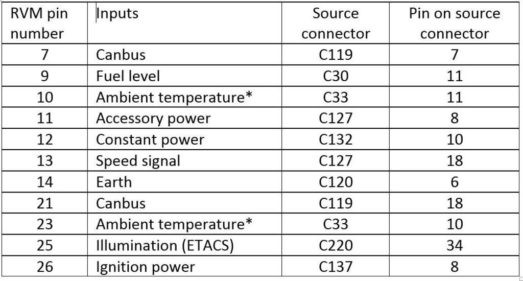
The cheat’s guide to connecting it all up I’ll deal with each connection in the order that they appear in the table above.
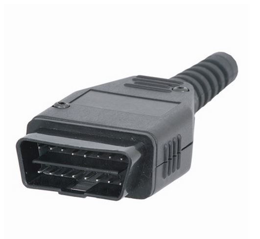
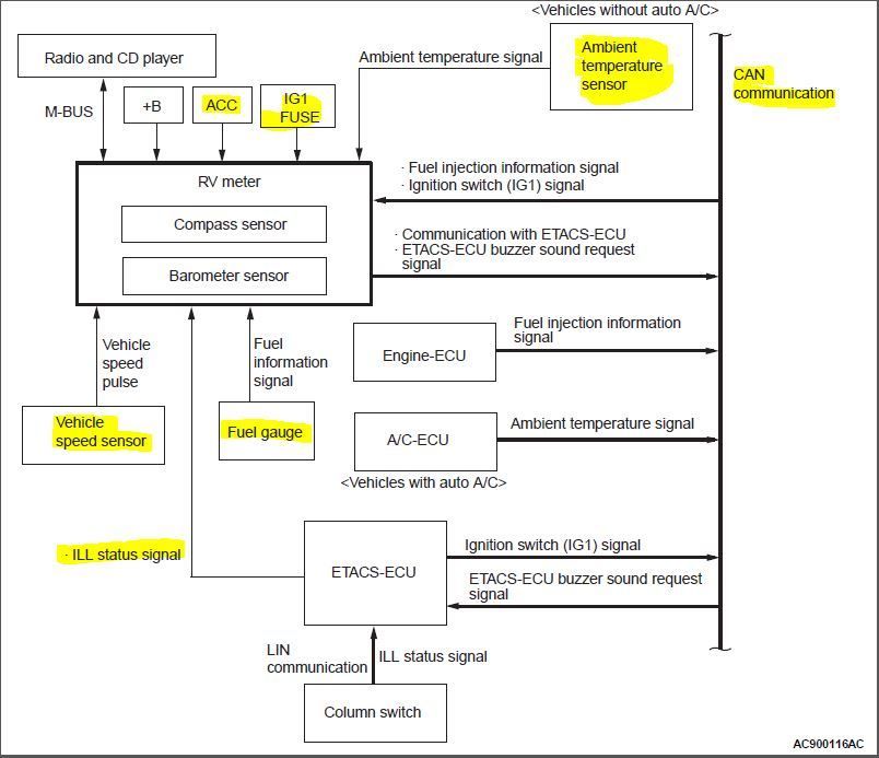
Pin 7 CANBUS (High) Since connecting to pin 7 on C119 is nigh on impossible, we use the OBD connector for this. In the canbus diagram in the PDF you will see that our pin 7 is on the same circuit as pin 6 of the OBD port/diagnosis connector.
The OBD layout looks like this:
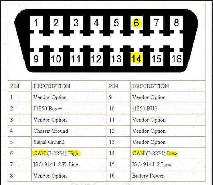
Pin 21 of our RV meter plug goes to pin 14 of the OBD connector. Once we have both connected we have CAN high and CAN low which is all we need from the 16 pins.
Now the workshop manual tells us that CANBUS wiring is all done in twisted pairs for shielding purposes. This is a PITA. I had some figure 8 wire (looks like light duty speaker wire) which was a low amperage Narva roll of wire. I basically peeled the two halves of the figure 8 wire to get two matching lengths of the same gauge wire and then twisted it all up into my own twisted pair.
You’ll need to solder 1 end of your twisted pair onto the pins of the 16 pin OBD connector. This is a pain, I am crap at soldering but I got there in the end. I taped the hell out of it where it exits the rear of the OBD plug to make sure none of it will ever move again.
On the other end I crimped two tiny little header connectors. I kept the receipt somewhere – another Jaycar item. 4wd trainer posted a pic of the ones to get in his brash imports install thread. I took that picture to Jaycar and they found the right packet for me. They really are crap to work with though. If you kept the cable lengths short you could probably get away with connecting these two the same way as I’ll describe for the other connections below.
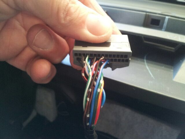
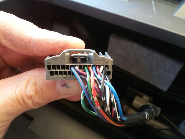
Pin 9 – Fuel gauge Connector C30 is the second one from the bottom behind the passenger side kick panel. Pin 11 is the 4th from the top closest to the outside of the vehicle. It should be green and black. I’ve just typed that from memory so check it against the diagrams in the PDF if it doesn’t look right.
The loom from this connector runs down and back along the door sill under the plastic trim. Remove the trim and you’ll see a big bundle with lots of black tape. I cut about a foot of tape off so I had a lot of room to work with. You can trace the wire back along the bundle and tease it out. You need to splice into this wire. I cut it and crimped bullet connectors to each end and in the front end I crimped not just the original wire but my extra wire for the RVM. Putting the bullets back together joins the original wire but now there is a piggyback connection for us to use. Heatshrink over the bullet connectors to ensure they can never come loose or get water inside etc
Don’t tape it back up yet as we come back to this loom later – see below (pin 18).
Pin 10 – Ambient temperature I looked at this and gave up straight away. I was really not keen on moving the ECU to get access. As it turns out I didn’t need to connect this at all (as I have climate control). Anyway it’s just easier to pull the grille off, remove the sensor from the radiator support panel, cut the wire, crimp in your piggy back wires, seal it all up again and then run the wire into the cabin. I used figure 8 cable again, this time 15 amp so it had a bit more thickness to it. You need two connections (the other is for pin 23) so do both at the same time. I ran the cable up behind the headlight then along the loom the MAF sensor goes to back to the firewall.
Pin 11 – Accessory power Here’s the thing. The RV meter has 3 separate power supplies. This is tedious but by design and it does different stuff depending upon where the ignition barrel is sitting at any given moment.
Now you might get as lucky as I did. I reckon you will. Get down near your gear sticks and look into the single din slot towards the right. On the right edge of the din slot you should see a single pink wire taped to the metal with a single blade terminal inside a white single pin plug. My testing showed this was a spare accessory power source. I used a small jewellers screwdriver to release the blade from the connector housing and then joined to the blade using a female crimp connector and stuck heatshrink over the top.
Pin 12 – Constant power Okay now things get a little dodgy but I’m game with the risks I’ve taken. I’ve done this before and never had a connection come loose. Your results may vary and you may choose to do this a different way. My way is quick and dirty and on this occasion it worked.
If you remove the dash panel below the steering wheel you will have good access to the fuse panel and relays. The layout looks like this:
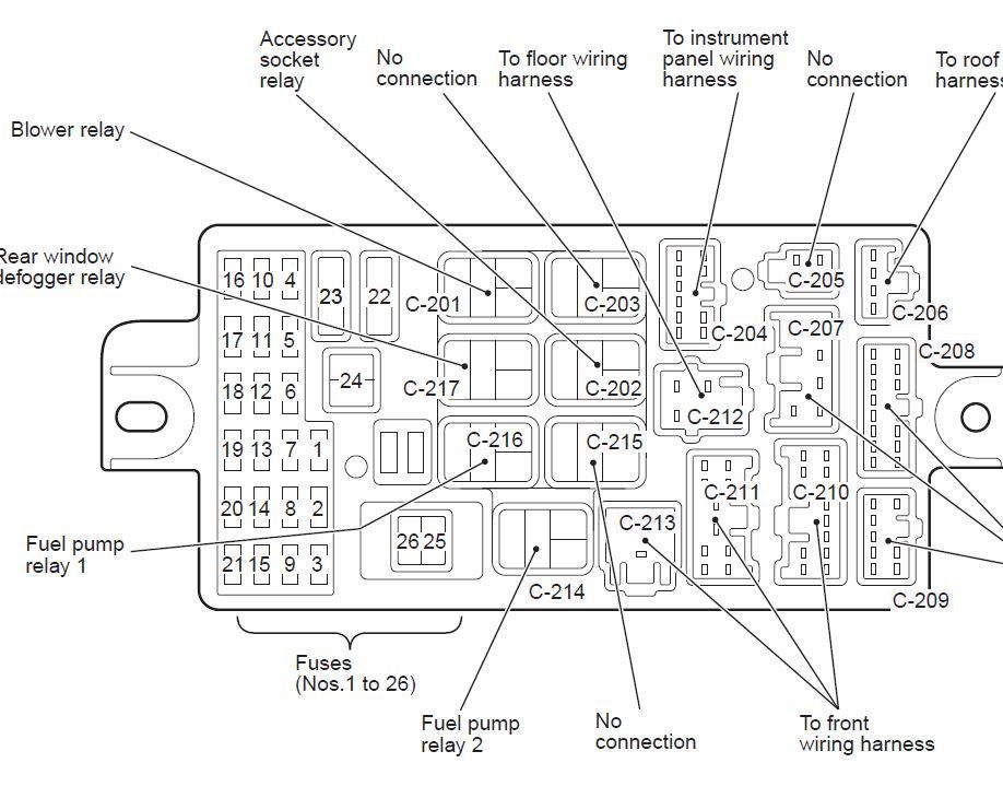
Some of the relay slots are empty but the pins within those slots are still live.
Have a look for relay spots C214 and C215. On my car they were both empty. On C215 the bottom right pin should be constant power – check it with a test lamp or multimeter to be extra sure.
If it is constant power as expected then a small male blade crimp terminal will push in there much the same way as a relay blade would. Heatshrink it all and push it in there good and tight. But don’t do this til the end or you will have live wire hanging around loose until you connect it all up to the R meter etc.
Pin 13 – Speed signal Go back to C30 where you picked up the fuel level signal. On the same plug is a white wire with pale blue trace. This is the speed signal wire. Much like the fuel level wire it runs back along the door sill which is why I said don’t tape it up again yet.
I spliced into this one exactly the same way as the fuel wire but offset it a bit from the other connection to make sure I didn’t have too big a bulge in the loom where all my joins were.
Don’t run this back to the RV meter until you read the next one but you can tape the loom back up and put the sill trim back on at this point if you want.
Pin 14 – EarthWhile you were working on C30 above, you might have noticed a small white connector next to it with several black wires all connected to an earth point at the bottom of the area behind the passenger kick panel. I crimped on a ring terminal and stuck my earth wire under that bolt.
Having done that I taped the speed signal wire, the fuel level wire and the earth together to make maybe a 4 foot cable run, pushed it up towards the ECU and then ran it along near the blower motor behind the glovebox and up to the RV meter area. I put coloured heatshrink on the end of each of the 3 wires so I could remember which one was connected to what later.
Pin 21 – CANBUS (low) See description under pin 7.
Pin 23 – Ambient temperature See description for pin 10
Pin 25 – illumination This is the only one I have any real doubts about. The manual says it gets a signal from the ETACS about illumination but as I read it I think they’re saying it gets two signals, one via canbus and one via a normal illumination signal. Anyway I just crimped another dodgy connection off the back of the small dash light that sits above the cigarette lighter. I already had some other connections in the same spot for the night lighting of some rocker switches anyway. You could choose somewhere else. Suffice it to say the RV meter didn’t shit itself when it received 12 volts on that pin so I’m guessing what I’ve done is okay.
Pin 26 – Ignition power See my description for pin 12. I found ignition power on C214 in the relay box – again it was the bottom right terminal but test it before using it as not all Tritons are the same.